JoeinCA
New member
Clone, yes i figure it out harder way but it worked loloriginal or clone ? on clone pinout is different , you know .
Следуйте инструкциям в видео ниже, чтобы узнать, как установить наш сайт как веб-приложение на главный экран вашего устройства.
Примечание: Эта функция может быть недоступна в некоторых браузерах.
Clone, yes i figure it out harder way but it worked loloriginal or clone ? on clone pinout is different , you know .
Thank you very much my friend, really based on your images there are no secrets, I did exactly this way respecting all your scheme and soldering points, but not the boot, I think this new board has the swclk, swdio and reset in different points. . .
I would like to see my device working with dz to know if it is capable of working with the canfd adapter cable for GM, as the mucar bt200 does not work with this adapter for this new protocol, understand...Thank you very much my friend, really based on your images there are no secrets, I did exactly this way respecting all your scheme and soldering points, but not the boot, I think this new board has the swclk, swdio and reset in different points. . .
Do you say remove the capacitor and try again? I also believe that the problem is not the capacitor, I believe that the soldering point scheme on the PCB is different (swclk, swdio and reset)if the capacitor bothers you, then solder out.
I don't think that's the problem.
I understand my friend, I'm going to wait for you to come across this new PCB lol and solve this little problem, but I really appreciate the care and attention you gave me with this procedure, thank you very much from the bottom of my heart.don't think the capacitor is a problem. Do not think it is another PCB, the soldering point would have to fit.
Посмотреть вложение 3731
Please tell me did you figure it out? I have the same board, I try according to the diagram above and it doesn’t connect.I understand my friend, I'm going to wait for you to come across this new PCB lol and solve this little problem, but I really appreciate the care and attention you gave me with this procedure, thank you very much from the bottom of my heart.
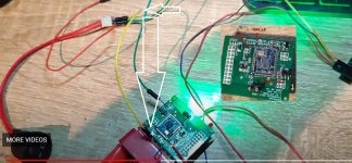
What is that yellow wire connected to and from ?Good, send step by step with pictures...
Если еще не собрали покажите фото платы с двух сторон .I got it! Was able to successfully flash the TD Mini VCI
The boards are same as theseWhen trying to download eobd at diagzone app, it gives "make your device working as pro you need upgrade microcode" error. But i could not find any soldering scheme of this board. Seller told me that this has old boot.
Посмотреть вложение 1783
Посмотреть вложение 1784
is thinkdiag mini can fd scannerpls can you explain hiw do that
But in the skorpion video the green LED does not turn off and a buzzing sound is heard when the connection occursI got it! Was able to successfully flash the TD Mini VCI but I had to do it the way in the video, not the way in the schematic. Without using the ground from the OBD connector there is not enough to cause the green light to go off or maybe because the STlink is not providing the power and ground it is not doing it. Either way for this to work the reset needs to be applied and when applied the greenlight must turn off just like the bt200. If the green light is not turned off then it's not going to work, In my case, I had to use the ground from pin 5 from the obd connector to connect to the reset with the switch/button, I grabbed it just like in the video from the back of the red obd2 connector at the solder ball/point same as the one you supplied ground to from the other/pin side. I also hooked up the reset from the STlink just because that's the way in the video and followed the instructions for the BT200 then was able to connect.
Thanks, Skorpi for the clarification!