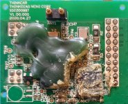
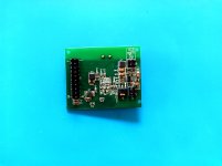
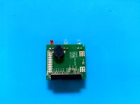
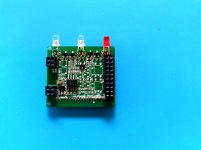
please if you completely your work tell us what happen
Установить приложение
Как установить приложение на iOS
Следуйте инструкциям в видео ниже, чтобы узнать, как установить наш сайт как веб-приложение на главный экран вашего устройства.
Примечание: Эта функция может быть недоступна в некоторых браузерах.
Вы используете устаревший браузер. Этот и другие сайты могут отображаться в нем неправильно.
Необходимо обновить браузер или попробовать использовать другой.
Необходимо обновить браузер или попробовать использовать другой.
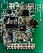
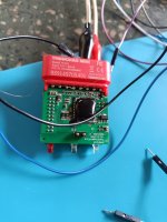
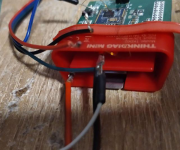
Thinkcar Pro Flashing Scheme
- Автор темы BatuhanK
- Дата начала
pls show more photo where clear
mhrm1
Member
Very good information my friend and this PCB... Look... Swdio and swclk?
Вложения
mhrm1
Member
Show your Bluetooth module
Вложения
mhrm1
Member
Show your Bluetooth module
Вложения
mhrm1
Member
No work my friend, you help me?The problem is, if you have flashed the firmware and something does not work, you can no longer flash back.
Вложения
mhrm1
Member
Very good my friend, could you tell me where I connect the positive and negative on the PCB? because through the 16-pin obd2 input, the device does not turn on to boot. Could you identify the positive and negative soldering points with photos? and are swclk, swdio and reset correct? If you can help with images I would be grateful and congratulations on the initiative.
mhrm1
Member
My reset uses direct stlink, but I have a question, do you power the device with 12v and the negative via the obd2 input? I did that too but it didn't work.Посмотреть вложение 3685
Pin 16 red == 12V positive
Pin 4/5 blue == GND negative
where is your reset connected?
mhrm1
Member
I easily change bt200, easydiag 3.0, thinkdiag 2, thinkcar pro... but I use all the connections I need directly from stlink, +, -, swclk, swdio and reset.
mhrm1
Member
Do you get the reset from the external power supply? make pin 4/5 gnd? I powered it externally with 12v like you did and it didn't boot, I used the direct reset from stlink, does that make any difference? From what I saw in your assembly you get the gnd 5/4, could that be it?
pls can you explain hiw do that
pls if any one know procedure can share with usWhat is not clear?

