Thincar Pro st link flashing problem [SOLVED]

  • Автор темы Автор темы sevo
  • Дата начала Дата начала

sevo

New member
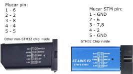
H all, i have been trying to flash my dongle with diagzone firmware but i can not connect it to the computer, when i press connect on ST Link Utility it says can not connect to target. I have followed the st link instructions for connecting the diagram as stated but still no luck, my st-link v2 programmer has a genuine st chip on it, i even ordered a new one and am waiting for it. I saw that some st link v2 clones come with geehy chip, not even STM32, and was wondering if with the fake ones will work. Any help and ideas are very welcome and highly appreciated. Thanks in advance
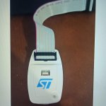
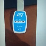
this is the dongle itself


on the picture you can see there is some glue, but i have managed to expose the pads carefully and solder some thin wires on them.
p.s i can not upload images for some reason :(
 
Последнее редактирование:
Hi. If you use original stlink and connected reset point on a board to reset pin on stlink you also should give 12 v to mucar 4 and 16 pin in obd connector
 
I have a green st-link with a different pinout, maybe you don't have the same pinout either. here is an example in the picture
088_ST-link_4-500x500.jpg
 
Hi. If you use original stlink and connected reset point on a board to reset pin on stlink you also should give 12 v to mucar 4 and 16 pin in obd connector
Do you mean pin 1 on st link which is RST, the instructions says that Reset from board should go to pin 5 which is not a RST on stlink!
So you suggest that i connect reset from board to pin 1 then supply additional 12V to pin 4 on mucar and 16 on OBD ? What about the 3.3V still supply them as well or? And also pin 4 on mucar is SWDIO on stlink what about that connection? it would burn the stlink and can damage the pc if i supply 12 to these pins? I don't understand, can you give me a diagram, also where is 12V GND connected as well? or do you mean to connect the dongle to the car and try to flash it this way?
 
Последнее редактирование:
12 and gnd must be fed to the obd2 connector
the rest of the contacts on the board according to the instructions, the reset on the board must be connected to the ground for a while before the connection is established, to stop the processor
 
Если оригинальный st-link, то во первых необходимо правильно определить пины на которые нужно подключаться, во вторых подать 12 вольт на сканер обд2(4,5 пин - gnd, 16 пин - +12 ). А также 19 пин ст-линка нужно пустить на 1пин.
 
"...the reset on the board must be connected to the ground for a while before the connection is established, to stop the processor"

I wanna apologize, i should have made myself clear in the beginning that i have the small usb flash drive like st link v2 adapter like this:
I have ordered 2 more, one with genuine chip and one with Geehy chip on it just to test and be sure that mine is not the problem.

but while looking at the images i think i have figured it out, when comparing the two st link adapters, the pins do not correspond, i was trying to reset the board with pin 5 connected to my pin 5 as per the instructions but i realized when you said that it should be to gnd that on my st link pin 5 is SWIM and not gnd, but on the ones with other chip, not genuine pin 5 is gnd, thats why it works with them and not with me, the pinout i used is not the correct one... thanks so much everyone, i will test it these days and give feedback as i am away from home for a week won't be able to do it now. One more time thanks a lot!!! Really appreciate your help
 

Вложения

  • Mucar BT200 pinout.jpg
    Mucar BT200 pinout.jpg
    227,8 КБ · Просмотры: 72
Последнее редактирование:
То что вы показали это китайская самоделка, а вот это ОРИГИНАЛ
 

Вложения

  • IMG_20220823_001536.jpg
    IMG_20220823_001536.jpg
    79,7 КБ · Просмотры: 34
  • IMG_20220823_001609.jpg
    IMG_20220823_001609.jpg
    85,9 КБ · Просмотры: 35
What you showed is a Chinese homemade product, but this is the ORIGINAL
You are absolutely right, while searching for a st link, i have discovered that even the clones come with fake chips, ( the clones have clones) because the chip used is not even STM32F1, but something else, thats why i said in my previous posts " the ones with genuine chip and with fake chip". And by the way it is really hard to find the original programmer, even from mouser, farnell etc. Thanks again for your help and clarification. Thats really helpful information for everyone.


UPDATE:
so i have managed to flash the VCI, bought diagzone and I am downloading the software now, really happy with everything so far, i hope that everything will work as expected, thanks again to everyone for your invaluable help!
 
Последнее редактирование:
You are absolutely right, while searching for a st link, i have discovered that even the clones come with fake chips, ( the clones have clones) because the chip used is not even STM32F1, but something else, thats why i said in my previous posts " the ones with genuine chip and with fake chip". And by the way it is really hard to find the original programmer, even from mouser, farnell etc. Thanks again for your help and clarification. Thats really helpful information for everyone.


UPDATE:
so i have managed to flash the VCI, bought diagzone and I am downloading the software now, really happy with everything so far, i hope that everything will work as expected, thanks again to everyone for your invaluable help!
I bought a Mucar Bt200 interface but I couldn't activate it with DZ,

How did you solve your problem with your interface?.....Could you help me how to reflash it? Please
 
Назад
Верх